An Ebike Cable is more than a simple wire linking two components. It may carry battery power, brake signals, display data, or motor commands. Some cables appear identical, yet their voltage ratings, connector designs, and communication protocols can differ sharply. That difference matters.
The market is expanding quickly. The International Energy Agency’s Global EV Outlook 2024 identifies electric two- and three-wheelers as the largest electrified road-vehicle segment by global stock. CONEBI’s European Bicycle Industry and Market Profile 2024 also shows how deeply e-bikes have entered everyday cycling across Europe. More bikes mean more attention to cable reliability, repairability, and safety. A loose connector can interrupt motor assistance beside a busy road. Moisture can enter a poorly sealed plug. Repeated handlebar movement can fatigue internal conductors.
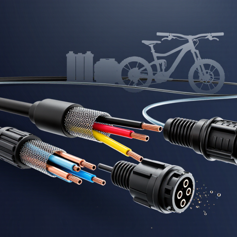
Inside an Ebike Cable, copper conductors transmit electrical energy or digital signals. Insulation separates circuits. Connectors maintain contact under vibration. Some systems add shielding against electromagnetic interference. Cable length also matters, because excessive length can increase resistance and signal loss. It is not always obvious.
Industry guidance, including UL 2849-based electrical safety practices, emphasizes system-level evaluation rather than judging one cable alone. The battery, controller, charger, motor, and wiring must work together. This article explains what an Ebike Cable does, how signals and power travel through it, and which design details influence performance. The terminology is not perfectly standardized. That can create confusion, even among experienced buyers and technicians. A careful inspection remains essential.
What Is an Ebike Cable and How Does It Work?
Ebike cables carry power and signals between the battery, controller, motor, display, and sensors. Inside each cable, copper conductors move electrical current or data. Thicker conductors usually handle higher current with less voltage loss. That detail matters.
Insulation surrounds the conductors and prevents short circuits, moisture contact, and accidental abrasion. Common insulation materials must remain flexible during steering and vibration. A cable may look strong, yet repeated bending near the handlebar can damage its internal strands. I have seen outer jackets remain intact while hidden conductors weaken. Small faults spread.
Connectors join cable sections and must match their pin layout, voltage, and signal purpose. A loose connector can cause intermittent power, display errors, or motor cutouts. Always check for bent pins, dirt, and incomplete locking before blaming the controller. Connector shape alone is not enough. Some similar-looking plugs carry different signals.
An IP rating describes resistance to dust and water under controlled testing. The first number measures solids, while the second measures water protection. A higher rating does not make a cable permanently waterproof. Pressure washing, damaged seals, and immersion can still allow water inside. Not always obvious. After riding in heavy rain, inspect low cable points and allow connectors to dry before reconnecting them. Wiring diagrams and service measurements provide better evidence than guesswork, although real-world wear can still challenge a perfect diagnosis.

This chart shows the theoretical DC resistance of one metre of conductor at 20°C. Values are calculated from standard material resistivity: approximately 0.01724 Ω·mm²/m for copper and 0.0282 Ω·mm²/m for aluminium. A larger conductor has lower resistance, which helps reduce voltage loss and heat. Real ebike cables may vary because of temperature, stranded construction, cable length, connector resistance, and insulation design.
An ebike cable typically contains metal conductors, polymer insulation, connectors, and an outer jacket. IP ratings describe enclosure protection: the first digit indicates protection against solids, while the second indicates protection against water.
An ebike cable carries electrical power between the battery, controller, and motor. In a 36–48 V system, thick power wires deliver direct current to the controller. The controller then regulates voltage and current before sending timed pulses to the motor. This controls speed, torque, and acceleration. A fully charged battery can exceed its stated voltage, so cable insulation and connectors must match the system.
Motor cables often include three thicker phase wires and several thin sensor wires. The phase wires carry high current, while sensor wires report rotor position to the controller. A loose connector can create heat, resistance, or sudden power loss. I once focused only on wire thickness and missed a partly damaged connector. That was a useful reminder: cable condition matters as much as cable size. Voltage drop also increases when cables are too long, thin, or poorly crimped.
Tips: Turn off the battery before inspection. Check polarity with a multimeter, not wire color alone. Look for melted plastic, loose pins, and stiff insulation. Keep connectors dry and firmly seated. If a cable becomes hot during normal riding, stop and investigate. Some faults are less obvious than expected.
An ebike cable carries either electrical power or control signals. Signal wiring is especially important because it connects sensors, displays, and controllers. A pedal sensor may receive a stable 5 V supply and return a changing voltage. The controller reads that voltage as pedal movement, speed, or brake status. A loose connector can create confusing symptoms.
CAN bus wiring works differently. It sends digital commands between electronic modules through a differential pair, usually called CAN-High and CAN-Low. These wires resist electrical noise better than a single signal wire. The controller may receive commands for assist level, battery information, or motor limits. Correct polarity, solid terminals, and suitable termination resistance are essential. CAN wiring is not simply “another 5 V cable.”
Tips: Switch off the battery before testing. Check the connector pinout first. Measure the 5 V reference against ground with a reliable multimeter. Do not inject voltage into an unknown CAN wire. Look for crushed insulation near the handlebar, where repeated movement causes hidden breaks. A twisted CAN pair should remain tightly routed, especially near motor power cables. In practice, cable colors are not always trustworthy. Pin numbers matter more. I have found that rushed visual checks miss intermittent faults; gently moving the harness during testing can reveal them. Still, this method needs care and should never replace the manufacturer’s wiring diagram.
An ebike cable is the electrical path between the battery, controller, display, and motor. Battery cables carry high current, so their construction matters more than appearance. Inside the battery, the Battery Management System, or BMS, monitors cell voltage, temperature, and current. It can disconnect power during overcharge, deep discharge, overheating, or a short circuit. That protection is essential, but it is not a substitute for correctly sized cables.
Current ratings need careful interpretation. A cable may tolerate a brief peak current but overheat during a long hill climb. The controller’s continuous demand, peak demand, cable length, conductor material, and surrounding temperature all affect sizing. Thicker conductors usually reduce resistance and voltage drop. They also stay cooler.
Small connectors can become the weak point. Watch them closely.
Heat leaves evidence.
During practical inspections, I check for softened insulation, darkened terminals, loose crimps, and unusual warmth after riding. A cool cable does not prove the design is perfect. Voltage drop can still reduce motor performance. I have also found that published current figures are sometimes misunderstood, especially when peak and continuous ratings are mixed. Use secure connectors, suitable insulation, and properly protected routing. Leave room for real-world conditions, because mud, vibration, and repeated bending gradually change a cable’s reliability.
An ebike cable carries battery power, sensor signals, or control commands between components. Its copper conductors, insulation, terminals, and connectors must work together. The U.S. Consumer Product Safety Commission reported 208 fire or thermal-runaway incidents involving e-bikes and e-scooters from 2017 through 2022, including at least 19 deaths (CPSC staff report, 2023). Cable testing cannot prevent every failure, but it can expose loose connections and damaged insulation early.
Power off. Disconnect the battery before continuity or resistance testing. Set the multimeter to continuity, then probe both ends of one conductor. A beep only shows a conductive path; it does not prove the cable is healthy. Wiggle the cable gently while testing. Intermittent readings often reveal broken strands near a connector. For resistance, short the probes first and record their lead resistance. Subtract that value from the cable reading. Long or thin cables naturally show more resistance. Never measure resistance on a live circuit.
Voltage-drop testing requires a powered system and careful probe placement. Measure directly across the cable or connector while the motor draws current. A rising reading suggests resistance at a terminal, crimp, or conductor. Keep probes insulated and away from moving parts. IEC 60364-6 recommends verifying protective measures and circuit performance during inspection, not relying on visual checks alone. I still recheck polarity before energizing a repaired cable. A small mistake can become an expensive lesson.
| Testing Area | What the Cable Does | Measurement or Specification | Typical Reference Value | Safe Testing Method | Interpretation |
|---|---|---|---|---|---|
| Power cable | Transfers battery power to the controller or another high-current component. | Nominal system voltage | 24 V, 36 V, 48 V, or 52 V DC systems are common | Set the multimeter to DC voltage. Probe the positive and negative conductors at an accessible connector without shorting them. | The measured voltage should be close to the battery’s present state of charge and should never exceed the meter’s selected range. |
| Signal cable | Carries low-current control or communication signals between components such as displays, sensors, and controllers. | Signal type | Low-voltage digital, analog, or sensor signals | Use the wiring diagram or service information before probing. Avoid applying an external voltage to an unknown signal pin. | An incorrect connection can damage electronic components even when the cable itself appears undamaged. |
| Continuity test | Confirms that a conductor forms an unbroken electrical path from one end to the other. | Resistance with the circuit de-energized | Usually near 0 Ω; the exact value depends on cable length, conductor size, and test-lead resistance | Disconnect the battery and isolate the cable from all electronic components. Select resistance or continuity mode, then test between matching terminals. | A beep or very low resistance generally indicates continuity. No reading or an overload indication suggests an open circuit. |
| Resistance test | Reveals excessive resistance caused by damaged strands, corrosion, loose terminals, or a poor crimp. | End-to-end conductor resistance | Should be low and stable; longer or thinner conductors normally measure more resistance | With power disconnected, measure the conductor end to end. Touch the meter probes together first and note the test-lead resistance. | A higher-than-expected or fluctuating value indicates a possible high-resistance connection or intermittent conductor. |
| Short-to-ground test | Checks whether a power conductor is unintentionally contacting the frame, shield, or another conductor. | Resistance between conductor and ground or between separate conductors | Normally very high resistance or no continuity when the circuit is isolated | Disconnect the battery and controller connections before testing. Never perform a resistance test on a powered circuit. | Low resistance may indicate insulation damage or a short circuit. Do not reconnect the battery until the fault is located. |
| Voltage-drop test | Shows how much voltage is lost across a cable, connector, fuse, or terminal while current is flowing. | Voltage difference under operating load | As low as practical; a noticeable increase compared with a known-good connection indicates unwanted resistance | Set the meter to DC voltage and measure directly across the cable or connection while the system is operating under a controlled load. Keep hands and probes clear of moving parts. | A larger voltage drop under load than at rest points to corrosion, a loose terminal, inadequate conductor size, or internal cable damage. |
| Connector inspection | Provides a detachable electrical interface between the battery, controller, motor, display, and sensors. | Mechanical and visual condition | Pins seated, clean, dry, aligned, and firmly retained | Remove power before inspection. Check for bent pins, discoloration, water entry, damaged seals, and loose locking mechanisms. | Heat marks, melted plastic, green corrosion, or loose pins can create resistance and intermittent operation. |
| Cable flex test | Identifies intermittent faults that occur when a cable moves at the handlebar, frame junction, or motor exit. | Continuity while gently moving the cable | Continuity should remain stable during careful movement | Use continuity mode with the system disconnected. Gently flex the cable near connectors and tight bends without pulling or sharply kinking it. | A changing reading or intermittent beep suggests a broken conductor, weak crimp, or damaged insulation. |
| Polarity check | Ensures positive and negative power conductors are correctly identified before reconnection. | DC voltage sign and terminal identification | Positive probe on positive terminal should produce a positive voltage reading | Verify the battery is connected only when the connector is safely accessible and the meter is set to an appropriate DC-voltage range. | A negative reading usually means the probes are reversed; incorrect polarity at a component can cause damage. |
| Insulation condition | Prevents conductors from contacting each other, the frame, moisture, or moving parts. | Physical condition and isolation | No cuts, exposed copper, crushing, abrasion, or water intrusion | Power down the ebike and inspect the complete cable route, especially steering points, frame openings, and areas near the motor. | Replace or properly repair damaged insulation. Do not rely on tape alone where the conductor or connector is mechanically compromised. |
| Meter safety | Protects the technician and the electrical system during measurement. | Correct mode, range, and probe connection | Voltage mode for live circuits; resistance or continuity only on de-energized circuits | Inspect leads, use a properly rated meter, start on a higher voltage range when uncertain, and avoid bridging adjacent terminals. | Never measure resistance or continuity on a powered cable. A misplaced lead or incorrect mode can create a short circuit. |
| After-test verification | Confirms that the cable and connectors are secure before normal riding. | Functional and physical check | Connectors locked, cables secured, steering unrestricted, and no fault symptoms present | Reassemble covers, secure cables away from tires and chains, switch the system on, and test brakes and controls at low speed in a safe area. | Stop using the ebike if the cable becomes hot, the system cuts out, sparks appear, or an error returns. |
You are using an outdated browser. Things may not appear as intended. We recommend updating your browser to the latest version.
Close