What Are the Top Mould Components for Global Buyers?

Choosing the right Mould Components can determine whether a production line runs smoothly or suffers repeated delays. Global buyers often compare prices first, but performance depends on details hidden inside the tooling. Guide pillars, ejector pins, cores, cavities, slides, and cooling parts must work together precisely. A low-cost component may create burrs, uneven surfaces, or unexpected maintenance expenses.

Experienced buyers examine more than catalog images. They check steel grades, hardness, dimensional tolerances, surface treatment, heat resistance, and expected service life. They also confirm compatibility with the mould structure and injection machine. For example, a poorly matched ejector pin can leave marks on a visible plastic housing. A weak guide system may produce alignment problems after thousands of cycles. Small errors become expensive.

Supplier reliability matters equally. Technical drawings, inspection records, material certificates, and sample testing can reveal important differences. Established manufacturers usually explain tolerance limits clearly and provide traceable quality documents. Still, no supplier is perfect, and no universal specification fits every project. This point deserves honest consideration. Some buyers may over-specify components and increase costs without improving product quality.

This guide explores the top Mould Components used by global manufacturers. It considers practical selection factors, common quality risks, and maintenance needs. The discussion focuses on evidence, workshop experience, and realistic purchasing decisions. Buyers can then compare components with greater confidence, especially when suppliers operate across different languages, standards, and production cultures. Good tooling is not merely a collection of parts. It is a controlled system built for repeatable results.
What Are the Top Mould Components for Global Buyers?

Understanding the Main Components of an Industrial Mould

An industrial mould begins with a rigid mould base, which supports every working part. The cavity and core create the product’s outside and inside surfaces. These hardened steel sections must match closely, especially around thin walls, sharp corners, and textured areas. Small errors appear as flash, uneven dimensions, or difficult ejection. Material choice matters.

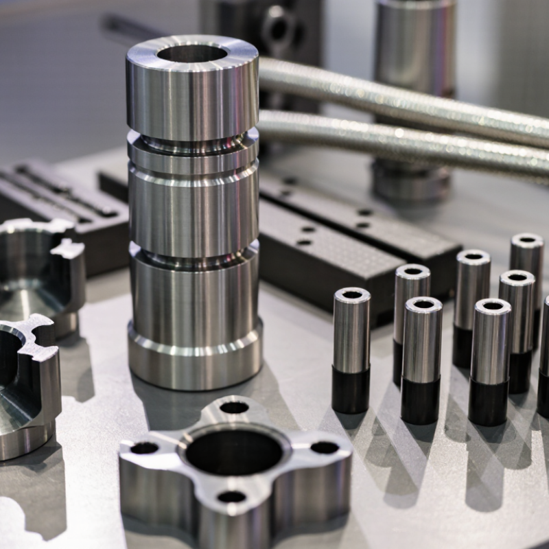
Guide pillars and bushings keep the two halves aligned during closing. Runner channels carry molten material from the sprue to each gate. Ejector pins, sleeves, and plates then release the cooled part without leaving unacceptable marks. Cooling channels control cycle time and reduce warping. Vents let trapped air escape near the final filling points. Slides and lifters handle side holes or undercuts that straight ejection cannot reach. That detail is often underestimated.

Global buyers should request component drawings, steel specifications, heat-treatment records, and dimensional inspection reports. During a factory review, check polished surfaces, pin movement, water-line connections, and spare-part access. A practical trial should measure cycle time, part weight, flash, and repeated fit. Photos help, but physical samples reveal more. No mould design is perfect forever. Maintenance planning can expose weak choices, such as narrow cooling channels or poorly supported inserts. Those choices may become expensive during a high-volume run.

Examining the Mould Base and Structural Support System

What Are the Top Mould Components for Global Buyers?

For global buyers, the mould base is more than a metal frame. It supports every insert, plate, guide, and cooling channel. A rigid base helps maintain alignment during repeated production cycles. Common structures include top and bottom clamping plates, support plates, cavity plates, and core plates. Each plate needs suitable thickness and flatness. Poor machining can create flash, uneven parting lines, or difficult maintenance. Small errors become expensive quickly.

Structural support also includes guide pillars, bushes, screws, locating rings, and ejector systems. These parts control movement and protect the mould from excessive stress. For example, properly positioned support pillars reduce plate deflection under injection pressure. Ejector plates should move smoothly without binding. I have seen designs that looked strong but lacked enough support near large cavities. They required changes after testing. That lesson is easy to overlook.

Tips: Check the steel grade, plate hardness, and surface treatment before approval. Ask for dimensional inspection records and a clear component drawing. Review cooling layout around thick mould areas. Confirm spare-part compatibility with your maintenance tools. Leave room for adjustment. Perfect drawings rarely survive the first trial unchanged. A practical design allows safe correction without rebuilding the entire base. Temperature, resin pressure, and cycle time should guide structural decisions, not appearance alone.

Comparing Cavity, Core, and Forming Inserts

For global buyers, mould performance often depends on three replaceable elements: cavity, core, and forming inserts. Each shapes a different surface, so treating them as interchangeable can create costly errors. The cavity defines the product’s exterior. It usually needs stable dimensions, polished surfaces, and reliable cooling near thick sections. The core forms internal geometry, including ribs, bosses, and holes. Its design must allow clean ejection without stressing thin walls. Small changes in draft can matter.

Forming inserts handle local details such as threads, logos, undercuts, seals, or sharp transitions. They are valuable when one area wears faster or product variants require quick replacement. Experienced buyers compare insert steel, hardness, heat treatment, and surface protection rather than price alone. They also request inspection reports, steel certificates, and dimensional records. A replaceable insert can shorten maintenance, but poor alignment may produce flash or mismatch lines. That risk deserves practical review.

Before ordering, check shrinkage assumptions, parting lines, cooling access, and machining allowances. Ask how the supplier will measure cavity-to-core alignment after assembly. For precision parts, coordinate-measuring results provide stronger evidence than verbal promises. Trial moulding should examine filling marks, ejection force, burrs, and cycle stability. Not every first trial will pass. Some specifications need revision after real material and temperature data appear. This is not failure; it is useful engineering feedback, though budgets should allow for it. Maintenance access should be considered before final approval.

What Are the Top Mould Components for Global Buyers? - Comparing Cavity, Core, and Forming Inserts

Mould Component Primary Function Typical Material Typical Hardness Typical Dimensional Tolerance Surface Finish Range Common Applications Key Buyer Considerations
Cavity Insert Forms the external surface and visible details of the moulded part. Pre-hardened tool steel, hardened tool steel, or corrosion-resistant mould steel. Approximately 28–52 HRC, depending on production volume and wear requirements. Usually ±0.01–0.05 mm for precision features; project requirements may vary. About Ra 0.05–1.6 µm, depending on polishing, texture, or machining requirements. Visible housings, covers, containers, automotive trim, medical components, and consumer products. Prioritise cosmetic quality, venting, cooling uniformity, steel corrosion resistance, and repairability.
Core Insert Forms the internal surfaces, cavities, holes, walls, and functional geometry of the part. Pre-hardened or hardened tool steel; corrosion-resistant steel is often selected for demanding environments. Approximately 28–52 HRC, with higher hardness used for abrasive materials or long runs. Usually ±0.01–0.05 mm for critical internal dimensions and alignment features. About Ra 0.10–1.6 µm; polished surfaces can improve part release and internal appearance. Internal bores, ribs, bosses, threaded features, fluid channels, and hollow moulded parts. Check draft angles, ejection clearance, core cooling, alignment, deflection control, and accessibility for maintenance.
Forming Insert Creates a local feature or replaceable detail such as a rib, logo area, texture, slot, or undercut. Tool steel, stainless mould steel, powder metallurgy steel, or carbide for highly abrasive details. Approximately 40–62 HRC, selected according to wear, impact, and moulding material. Usually ±0.005–0.03 mm for replaceable precision details. About Ra 0.05–1.6 µm, including polished, machined, etched, or textured surfaces. Interchangeable details, serial-number areas, special textures, thin ribs, inserts, and high-wear regions. Evaluate interchangeability, locking method, thermal expansion, spare-part availability, and ease of replacement.
Slide or Lif ter Insert Produces side actions, undercuts, lateral holes, and features that cannot release in the main opening direction. Pre-hardened or hardened tool steel with wear-resistant sliding surfaces. Approximately 38–54 HRC. Typically ±0.01–0.04 mm for mating and functional features. About Ra 0.20–1.6 µm on sliding and forming surfaces. Snap-fits, side holes, hooks, handles, undercuts, and complex external geometry. Review stroke length, lubrication, wear plates, locking strength, timing, and risk of flash at shut-off surfaces.
Gate Insert Controls the entry of molten plastic into the cavity and helps define the gate mark. Hardened tool steel or wear-resistant steel. Approximately 45–60 HRC. Typically ±0.005–0.02 mm at the gate and sealing interface. About Ra 0.10–0.80 µm in the melt-flow area. Hot-runner systems, cold-runner systems, precision parts, and applications requiring controlled gate appearance. Confirm gate type, resin compatibility, shear sensitivity, maintenance access, and replacement procedure.
Wear Insert Protects high-wear or high-impact areas and allows damaged sections to be replaced without rebuilding the full mould. Hardened tool steel, powder metallurgy steel, carbide, or other wear-resistant alloys. Approximately 50–65 HRC, depending on the selected material and heat treatment. Typically ±0.01–0.03 mm for mating and forming surfaces. About Ra 0.10–1.6 µm. Glass-filled plastics, abrasive compounds, repeated shut-offs, thin edges, and high-cycle moulds. Compare wear resistance, toughness, brittleness, coating compatibility, replacement cost, and expected service life.
Note: The values shown are typical engineering ranges for injection-mould components. Actual tolerances, hardness, surface finish, and material selection should be confirmed against the part drawing, resin specification, production volume, and moulding process.

Reviewing Ejection, Cooling, and Runner Components

What Are the Top Mould Components for Global Buyers?

For global buyers, mould performance often depends on three quiet systems: ejection, cooling, and runner control. Ejection components release the part without whitening, distortion, or stubborn marks. Ejector pins, sleeves, blades, and return elements must match the product geometry. A pin near a thin rib may leave a visible witness mark. Too much force can bend a delicate part. In practical mould reviews, balanced pin layouts usually reduce sampling problems. Still, no layout works universally. Material shrinkage changes the decision.

Cooling components influence cycle time and dimensional stability. Channels should follow heat concentration, not simply mirror the cavity outline. Baffles, bubblers, plugs, seals, and connectors need clear maintenance access. Poorly positioned water circuits create hot corners and uneven gloss. Use pressure and flow checks during trials. A temperature reading alone can mislead. That lesson is easy to overlook. Buyers should request cooling maps, leak tests, and replaceable component details before approval.

Runner components guide molten material toward each gate. Sprue bushes, runners, gates, and nozzle interfaces require careful alignment. For multi-cavity moulds, runner balance supports consistent filling and part weight. A polished runner is not automatically a well-designed runner. I would also check steel grade, hardness, dimensional reports, and spare-part compatibility. Small errors become expensive during long production runs. A perfect drawing can still hide poor maintenance access. That deserves honest review.

Evaluating Materials, Standards, and Sourcing Needs for Global Buyers

What Are the Top Mould Components for Global Buyers?

Global mould buyers usually assess the complete system, not isolated parts. Core components include mould bases, cavity inserts, guide pillars, ejector pins, cooling fittings, and hot-runner interfaces. Material selection should match production volume, resin behavior, and maintenance conditions. Hardened tool steel suits abrasive resins and repeated cycles. Pre-hardened steel can reduce machining time for medium-volume work. Stainless steel helps resist corrosion near humid production areas. Traceability matters. Each critical component should carry a material certificate, heat number, and inspection record.

Standards make distant sourcing more predictable. Buyers should request dimensional reports against agreed drawings, surface-finish values, hardness results, and functional checks. ISO 9001 remains a useful screening signal; the ISO Survey 2023 recorded more than 1.26 million valid certificates across 189 countries and economies. However, certification alone cannot prove mould accuracy. A poorly controlled cavity still fails, even with polished paperwork. For plastics-related testing, buyers can reference ISO 294 for processing conditions and ASTM methods where regional teams already use them.

Sourcing decisions also need logistics planning. UNCTAD’s Review of Maritime Transport 2024 notes that shipping carries over 80% of world merchandise trade by volume. Protect precision parts with corrosion paper, sealed packaging, and shock indicators. Ask for spare ejector pins and standard fasteners. Small parts can stop a large mould. Some buyers over-specify every component, increasing cost without improving tool life. That deserves review. A practical specification should separate safety-critical tolerances from replaceable, standard items.

Warning!

You are using an outdated browser. Things may not appear as intended. We recommend updating your browser to the latest version.

Close