What Is a Valve Actuator and How Does It Work?

A Valve Actuator converts control signals into mechanical movement, allowing a valve to open, close, or regulate flow. It may use electric power, compressed air, or hydraulic pressure. In a plant, that movement can control water, steam, oil, gas, or corrosive chemicals. The mechanism sounds simple. The responsibility is not. A few degrees of incorrect travel can affect pressure, temperature, safety, and production quality.

Industry data shows why this technology remains important. MarketsandMarkets’ Industrial Valves Market report identifies automation, energy infrastructure, and process industries as major growth drivers. Grand View Research also reports continued expansion in industrial automation and control equipment, supported by smarter manufacturing systems. However, market estimates differ because companies classify actuators, control valves, and accessories differently. That inconsistency deserves attention.

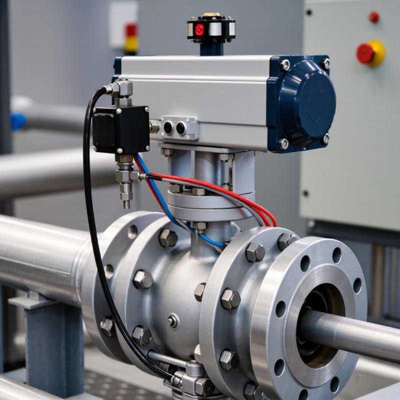
This guide explains how a Valve Actuator works, from the command signal to the final stem or shaft movement. It examines electric motors, pneumatic cylinders, hydraulic systems, torque, fail-safe operation, and position feedback. Standards such as ISO 5211 and IEC 60534 help engineers match actuators with valve interfaces and control requirements. A practical example is a pneumatic actuator mounted above a butterfly valve. Air enters the cylinder, the piston moves, and the valve disc rotates inside the pipeline. Sensors then confirm its position. Small movement. Large consequence. No actuator is perfect, especially when sizing ignores temperature, friction, cycling frequency, or emergency requirements. Reliable selection depends on verified data, field experience, and careful maintenance records.
What Is a Valve Actuator and How Does It Work?

What Is a Valve Actuator and What Purpose Does It Serve?

A valve actuator is the mechanism that opens, closes, or positions a valve. Its main purpose is to control fluid or gas flow without constant manual effort. In a processing line, it can respond to a control signal within seconds. The actuator may use electric power, compressed air, or hydraulic pressure. Each option suits different operating conditions. Electric models support precise positioning and easy system integration. Pneumatic models often provide fast movement in demanding industrial areas. Hydraulic units deliver high force for large, tightly sealed valves. The choice depends on valve size, torque, speed, and available energy.

Inside the actuator, a motor, piston, or drive mechanism produces movement. A gearbox may increase torque and reduce operating speed. The actuator then transfers this force to the valve stem or shaft. Sensors can confirm whether the valve is open, closed, or partly positioned. This feedback helps prevent unsafe flow changes and reduces manual inspection. However, an actuator is not automatically reliable after installation. Incorrect sizing can cause weak movement, overheating, or premature wear. Moisture, dirt, and unstable pressure can also affect performance. I have found that simple commissioning checks often reveal overlooked alignment problems. Maintenance teams should inspect connections, travel limits, seals, and response time regularly. A small adjustment can prevent a costly process interruption.

What Is a Valve Actuator and How Does It Work? - What Is a Valve Actuator and What Purpose Does It Serve?
Actuator Type Energy Source Output Motion Commonly Used With How It Works Main Advantages Typical Limitations Common Fail-Safe Arrangement
Manual Actuator Human effort Rotary or linear
  • Gate valves
  • Globe valves
  • Ball valves
  • Butterfly valves
A handwheel, lever, or gearbox transfers operator input to the valve stem or shaft.
  • Simple construction
  • No external power required
  • Low installation cost
  • Requires local operation
  • Slow for frequent adjustments
  • Not suitable for remote control
Normally remains in its last manually selected position.
Pneumatic Actuator Compressed air or gas Rotary or linear
  • Ball valves
  • Butterfly valves
  • Globe valves
  • Control valves
Air pressure acts on a piston or diaphragm to produce force and move the valve. Springs may return the valve when air pressure is removed.
  • Fast response
  • Suitable for hazardous areas when properly configured
  • High power-to-weight ratio
  • Requires a clean, reliable air supply
  • Air preparation and tubing are needed
  • Position accuracy may require additional accessories
Spring-return designs can be configured to fail open or fail closed when air pressure is lost.
Electric Actuator Electrical power Rotary or linear
  • Ball valves
  • Butterfly valves
  • Gate valves
  • Globe valves
An electric motor drives a gearbox, screw, or stem mechanism. Limit switches, torque protection, and position sensors control movement.
  • Precise positioning
  • Easy integration with control systems
  • No compressed-air system required
  • Generally slower than pneumatic operation
  • Requires electrical protection in hazardous environments
  • Motor and gears may need maintenance
May remain in position, move to a defined position, or use a backup spring or battery system, depending on the design.
Hydraulic Actuator Pressurized hydraulic fluid Rotary or linear
  • Large ball valves
  • Large butterfly valves
  • Gate valves
  • High-force isolation valves
Hydraulic pressure acts on a piston or vane to create high force or torque for moving the valve.
  • Very high force capability
  • Good control of large valves
  • Suitable for demanding industrial applications
  • Requires a hydraulic power unit or fluid supply
  • Fluid leaks can affect reliability and cleanliness
  • Installation is more complex
Spring-return or stored-energy systems can provide fail-open or fail-closed action when hydraulic pressure is lost.
Quarter-Turn Actuator Manual, pneumatic, electric, or hydraulic power Approximately 90-degree rotation
  • Ball valves
  • Butterfly valves
  • Plug valves
The actuator rotates the valve shaft through a limited angle to move the closure element between open and closed positions.
  • Compact design
  • Rapid operation
  • Well suited to on/off service
Not suitable for valves that require multiple turns or long linear stem travel. Can use a spring-return mechanism or other stored energy to reach a safe position.
Multi-Turn Actuator Manual, electric, or hydraulic power Multiple rotations
  • Gate valves
  • Globe valves
  • Rising-stem valves
The actuator rotates the stem or stem nut through several turns, producing linear movement and seating force.
  • Suitable for long stem travel
  • Can generate substantial thrust
  • Supports accurate end-position control
Usually requires more space and takes longer to operate than quarter-turn equipment. Fail position depends on the actuator design, valve load, and any installed backup or spring mechanism.
Modulating Actuator Electrical, pneumatic, or hydraulic power with a control signal Continuous rotary or linear adjustment
  • Control valves
  • Characterized ball valves
  • Butterfly valves
  • Globe valves
A controller compares the desired process value with feedback and adjusts the valve position to regulate flow, pressure, temperature, or level.
  • Automatic process regulation
  • Remote operation
  • Position feedback can improve control accuracy
  • More complex than on/off actuation
  • Requires suitable sizing and tuning
  • Frequent movement may increase wear
Often configured to fail open, fail closed, or fail in place according to process safety requirements.
On/Off Actuator Manual, pneumatic, electric, or hydraulic power Movement between defined end positions
  • Isolation valves
  • Emergency shutdown valves
  • Process diversion valves
The actuator drives the valve fully open or fully closed in response to a local or remote command.
  • Simple control logic
  • Reliable isolation
  • Suitable for emergency shutdown service
Does not normally provide precise flow regulation and may cause process shock if operated too quickly. The selected safe position depends on whether continued flow or stopped flow is safer for the process.
Key Selection Factors Process requirements and available utilities Quarter-turn or multi-turn; rotary or linear Valve type, size, pressure rating, and service conditions Selection involves matching required torque or thrust, operating speed, control method, duty cycle, environmental conditions, and valve travel.
  • Improves operational reliability
  • Supports safe and efficient valve operation
  • Helps prevent undersizing and excessive wear
Incorrect sizing or unsuitable materials can cause slow operation, incomplete travel, leakage, or premature failure. Choose the fail position based on the hazards and consequences of loss of power, air, hydraulic pressure, or control signal.
Purpose of a valve actuator: A valve actuator converts manual or external energy into controlled mechanical movement, allowing a valve to start, stop, isolate, or regulate the flow of liquids, gases, and vapors. Actuators may be operated locally or integrated with an automated control and safety system.

How Does a Valve Actuator Convert Energy Into Valve Movement?

What Is a Valve Actuator and How Does It Work?

How Does a Valve Actuator Convert Energy Into Valve Movement?

A valve actuator converts external energy into controlled mechanical movement. It may use compressed air, electricity, or hydraulic pressure. The actuator transfers this force through a shaft, gear train, or linkage. That movement turns a rotary valve or pushes a linear valve stem.

With a pneumatic actuator, compressed air enters a chamber and moves a diaphragm or piston. The piston creates torque that rotates the valve disc.

An electric actuator uses a motor, reduction gears, and position sensors. The gears reduce speed but increase turning force.

Hydraulic designs use pressurized fluid when high operating torque is necessary.

The process must match the valve’s size, pressure, and operating conditions. A technician checks required torque, stroke length, cycle speed, and temperature range. A small mismatch can leave the valve partly open. That can cause leakage, unstable flow, or unnecessary wear.

Feedback systems improve control. A sensor reports the valve position to the controller, which adjusts the actuator’s movement. Many systems also include a spring-return function. If power or air pressure fails, the spring moves the valve toward a safer position.

Field experience shows that alignment matters. Even a strong actuator can perform poorly against a bent stem or excessive packing friction. I have also seen specifications treated as exact answers, although real installations vary. Dirt, cold temperatures, and frequent cycling can change performance over time. Regular inspection remains essential.

What Are the Main Types of Valve Actuators?

What Is a Valve Actuator and How Does It Work?

A valve actuator converts energy into controlled valve movement. It may rotate a ball valve or move a gate valve in a straight line. The actuator receives a signal from a control system, then applies torque or thrust. Limit switches and position sensors help confirm the valve’s actual position. In real installations, correct sizing matters more than appearance. A small error can leave a valve partly closed.

What Are the Main Types of Valve Actuators?

Pneumatic actuators use compressed air to produce quick, reliable movement. They suit process lines where fast cycling and simple maintenance are important. Electric actuators use a motor and gears, offering accurate positioning without an air supply. They work well when electrical control and slower adjustment are acceptable. Hydraulic actuators deliver high force from pressurized fluid. They are useful for large valves, but leaks and fluid cleanliness require attention.

Electro-hydraulic actuators combine electrical signals with hydraulic power. This arrangement can provide strong movement and precise control in demanding systems. Manual actuators, such as handwheels and gear operators, remain practical for infrequent operation. They depend on human access and physical effort.

The best choice is not always obvious. Temperature, valve size, operating speed, available utilities, and required fail-safe action must be checked together. A pneumatic unit may fail safely with a spring return, while an electric unit may need backup power. Field conditions can expose assumptions. Dust, moisture, corrosion, or limited space may change the decision. Verification during commissioning is essential.

Which Components Control and Support Actuator Operation?

A valve actuator converts a control signal into movement, but several supporting components determine whether that movement is accurate and safe. The power source may be compressed air, electricity, or hydraulic pressure. A gearbox adjusts speed and torque, while the stem coupling transfers force to the valve. In pneumatic systems, a solenoid valve directs air into the actuator chamber. In electric systems, a motor controller manages rotation and braking.

Positioners deserve close attention. They compare the commanded position with feedback from a sensor, then correct small errors. Limit switches confirm fully open or closed travel. Torque switches stop movement when resistance becomes excessive. A spring-return mechanism can move the valve toward a safer position after power or air loss. Enclosures also matter, especially where dust, moisture, or temperature changes threaten wiring and sensors.

The 2024 Fortune Business Insights valve actuator analysis valued the global market at approximately USD 8.6 billion in 2023 and projected continued growth through 2032. That expansion reflects rising demand for automated flow control, not merely larger motors. ISO 5211 dimensional guidance also helps match actuators with valve mounting interfaces, reducing alignment problems. Still, a compliant connection does not guarantee reliable operation. Field inspections often reveal loose terminals, poorly adjusted switches, or feedback signals that drift over time. Small faults become expensive quickly. Test the complete control chain, not only the actuator.

Valve Actuator Control and Support Components

Standard linear mapping between a 4–20 mA control signal and valve position. The same signal range is commonly used for position feedback.

A controller or PLC sends the command signal to the actuator’s drive or positioner. The actuator converts electrical, pneumatic, or hydraulic energy into mechanical motion. A position sensor provides feedback, while limit switches, torque protection, the power supply, and the valve mounting hardware support safe and reliable operation.

How Should Valve Actuators Be Selected and Maintained?

A valve actuator converts control signals into mechanical movement, opening, closing, or positioning a valve. Selection should begin with the valve’s torque or thrust requirement, not the actuator’s advertised size. Calculate breakaway torque, running torque, shutoff load, cycle frequency, temperature, and corrosion exposure. Add a documented safety margin, but avoid excessive oversizing. A larger actuator can increase cost, energy use, and mechanical stress.

Pneumatic actuators suit fast, repetitive operation when clean instrument air is available. Electric units often simplify installation where air systems are impractical. Hydraulic actuators provide high force, but fluid leakage and temperature control require attention.

The U.S. Department of Energy reports that compressed-air leaks can waste 20–30% of compressor output, making air-quality checks financially important. IEC 60534 and ISO 5211 provide useful guidance for control valves and actuator interfaces. Still, standards do not replace site testing. Real friction may differ from design assumptions.

Tips: Record operating torque during commissioning, then compare it during scheduled inspections. Inspect couplings, stem alignment, seals, limit switches, and position feedback. Check pneumatic filters and regulators; moisture can quietly damage components. For electric actuators, verify wiring, enclosure integrity, and travel calibration. Review cycle counts and alarm history before failure occurs. Maintenance teams often focus on the actuator and overlook the valve seat. That is a mistake. Also, a “perfect” maintenance interval rarely exists; process duty, contamination, and seasonal temperature changes should refine it. Use documented evidence, not habit.

Warning!

You are using an outdated browser. Things may not appear as intended. We recommend updating your browser to the latest version.

Close