What Are Machined Parts and How Are They Made?

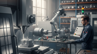
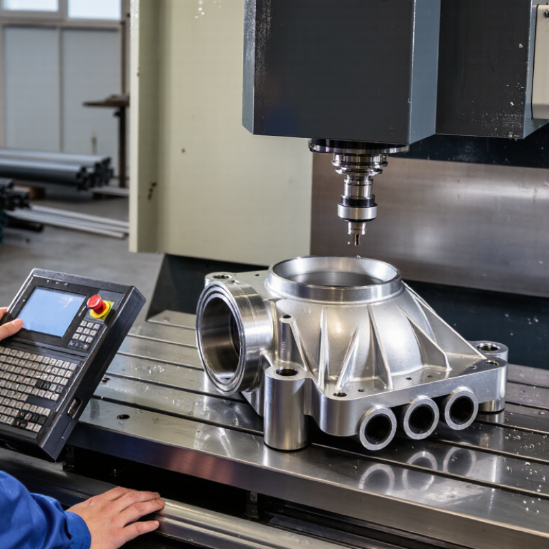
Machined parts are shaped by removing material from metal, plastic, or other solid stock. A cutting tool follows a digital model, engineering drawing, or production fixture. The result may be a small shaft, a threaded housing, or a complex aerospace bracket. Each part carries evidence of its process: tool marks, tolerances, surface finish, and inspection records.

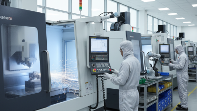
The manufacturing sector remains economically significant. The World Bank reports that manufacturing value added represented about 16% of global GDP in recent years. Its importance reaches far beyond factories. Machined parts support medical devices, vehicles, robotics, energy equipment, and industrial machinery. Deloitte’s 2024 Smart Manufacturing and Operations Survey found that 86% of manufacturing executives view smart manufacturing as a major competitiveness driver within the next three years. That pressure is changing machine shops. CNC equipment now connects programming, cutting, measurement, and production data more closely.

Yet software does not replace judgment. Real shops are messier. A machinist may adjust a tool after hearing vibration or seeing a rougher edge. Material hardness, heat, coolant flow, and fixture stability can alter the final result. This is where manufacturing experience matters. The process often includes design review, material selection, CNC programming, setup, cutting, deburring, cleaning, and dimensional inspection. Some steps are automated. Others still depend on trained hands.

This article explains what machined parts are, how manufacturers produce them, and why tolerance control matters. It also examines common machining methods, suitable materials, quality checks, and practical cost factors. The definition is useful, but incomplete without the shop floor.
What Are Machined Parts and How Are They Made?

What Are Machined Parts?

Machined parts are components shaped by removing material from a solid block, bar, or sheet. The process can create precise holes, threads, slots, and complex contours. Common materials include aluminum, steel, brass, titanium, and engineering plastics. Cutting tools move against the workpiece through turning, milling, drilling, grinding, or electrical machining. Each method leaves different surface characteristics and dimensional limits.

A machinist usually begins with an engineering drawing and a material certificate. The drawing defines critical dimensions, tolerances, surface finish, and reference points called datums. These details guide tool selection, fixture design, cutting speed, and inspection. Calipers may check general dimensions, while micrometers or coordinate measuring machines verify tighter features. Burr removal matters too. A tiny burr can prevent two parts from seating correctly.

Machined parts appear in medical equipment, vehicles, automation systems, pumps, and structural assemblies. Their value comes from controlled geometry, not appearance alone. A bright surface may still hide an incorrect hole position. In practice, the first drawing is rarely perfect. Designers sometimes overlook tool access, material movement, or difficult internal corners. Experienced manufacturers question those details before cutting metal. Even then, results can vary with machine condition, operator judgment, temperature, and measurement technique. That uncertainty deserves attention. Small production changes can expose weak assumptions, especially when a prototype becomes a high-volume component.
What Are Machined Parts and How Are They Made?

Machined parts are components shaped by removing material from a solid workpiece. The chart shows typical dimensional tolerance capabilities for common machining processes. Lower values indicate tighter control, while actual results depend on the machine, material, tooling, and inspection method.

Typical tolerance values shown in millimeters; they are general industry ranges rather than universal specifications.

Which Materials Are Used for Machined Parts?

Machined parts are made from materials that respond predictably to cutting, drilling, turning, and milling. Aluminum is widely selected for housings, brackets, and lightweight frames. The 2024 USGS Mineral Commodity Summaries reported approximately 70 million metric tons of primary aluminum production in 2023. Its low density and natural oxide layer help reduce weight and corrosion. However, aluminum can smear during cutting when tools are dull or cooling is poorly controlled.

Steel Steel remains essential when parts need high strength, wear resistance, or stable dimensions. The World Steel Association reported about 1.89 billion tonnes of crude steel production in 2023. Carbon steel suits shafts and fixtures, while stainless steel supports damp or chemically exposed environments. Machinists still check hardness, heat-treatment condition, and material certificates before production. A familiar grade can behave differently after heat treatment.

Titanium offers an impressive strength-to-weight ratio, but it generates heat near the cutting edge. It demands rigid workholding, sharp tools, and conservative cutting parameters. Brass machines smoothly and often appears in fittings, bushings, and electrical components. Engineering plastics, including acetal and nylon, reduce friction and electrical conductivity, though they may deform under heat or clamping pressure. Material selection is not only about price. Surface finish, tolerance, production volume, and end-use temperature can change the decision. A material chart helps, but shop-floor testing sometimes exposes assumptions that looked correct on paper.

How Are Machined Parts Designed and Prepared?

Machined parts begin with a manufacturable design, not merely an attractive 3D model. Engineers define datums, critical dimensions, surface finishes, and geometric tolerances before selecting cutting tools. A clear drawing tells the machinist what matters and what can vary. Small errors matter. Over-tight tolerances can increase machining time, inspection effort, and material waste. The designer should question every decimal place.

Material selection follows the part’s function and production method. Aluminum may reduce weight, while hardened steel can improve wear resistance. However, hardness changes tool life and cutting conditions. Designers also check wall thickness, hole depth, internal corners, and tool access. A narrow pocket may look simple in CAD but remain difficult to machine. The design review should include an experienced programmer or machinist.

Digital preparation converts design intent into controlled production instructions. CAM software generates toolpaths, while post-processing creates machine-specific code. Simulation can reveal collisions, excessive tool engagement, or unreachable surfaces before cutting begins. The International Federation of Robotics reported 541,302 new industrial robots installed worldwide in 2023, showing how strongly manufacturing depends on precise digital preparation. Yet automation cannot repair unclear requirements. A 2024 manufacturing technology survey also found that data quality remains a major obstacle to smart-factory progress. That warning deserves attention. Before release, teams verify revisions, materials, tolerances, inspection points, and workholding assumptions. A drawing can still be wrong. Physical trial cuts and measurement feedback often expose weaknesses that software misses.

What Steps Are Involved in Machining a Part?

Machining a part begins with a drawing, not a cutting tool. An engineer checks dimensions, tolerances, surface finish, material, and critical datums. The model then becomes a process plan. Stock size, workholding, cutting tools, speeds, feeds, and inspection points are selected. A small mistake here can multiply later.

The International Organization for Standardization’s 2022 survey recorded more than one million ISO 9001 certificates worldwide. That figure explains why documented inspection matters. Operators often verify raw material, secure the workpiece, set machine offsets, and run a controlled first piece. Then the cut begins. Computer-aided manufacturing software generates toolpaths, but experienced machinists still review clearances and chip evacuation. A perfect simulation is not a perfect part.

Roughing removes bulk material quickly, leaving allowance for finishing. Finishing passes create the specified geometry and surface texture. Holes may require drilling, boring, reaming, or threading. After machining, inspectors measure features with calipers, micrometers, gauges, or coordinate measuring equipment. The International Federation of Robotics reported 553,052 industrial robot installations in 2022, showing how automation increasingly supports loading and repeatable production. It does not remove judgment. Heat, tool wear, vibration, and imperfect clamping can still change results. The honest process includes rechecking the setup.

How Are Machined Parts Inspected and Finished?

Inspection begins with the engineering drawing, not with guesswork. In a real machine shop, technicians verify dimensions using calibrated micrometers, gauges, and coordinate measuring machines. Critical diameters may be checked at several points to detect taper or ovality. Small errors matter. Inspectors also examine hole locations, thread quality, flatness, and perpendicularity. These details determine whether a machined part fits and performs safely.

Surface condition receives equal attention. A roughness tester can measure the texture left by cutting tools, while strong lighting reveals burrs, chatter marks, and small dents. Visual inspection catches problems that instruments may miss. Not every scratch is unacceptable, but its location and depth must match the drawing. Inspection records should identify the measurement method, equipment, result, and operator. When results conflict, the part should be measured again under stable temperature conditions. That step is sometimes overlooked.

Finishing may include deburring, polishing, shot blasting, or a protective coating. Deburring is not merely cosmetic; a sharp edge can damage seals or injure a handler. Polishing can improve appearance, but excessive material removal may change a critical dimension. Anodizing, plating, or painting may also alter fit, especially in tight assemblies. Final inspection should follow finishing, because coatings and polishing can change thickness or surface roughness. No process is perfect. Even experienced teams can miss a faint burr inside a hole, so tactile checks and sectional sampling remain valuable.

What Are Machined Parts and How Are They Made? - How Are Machined Parts Inspected and Finished?

Process or Stage How It Works Common Features Produced Typical Dimensional Capability* Typical Surface Roughness Range* Primary Inspection Method Possible Finishing Steps
CNC Milling A rotating cutting tool removes material from a fixed workpiece along multiple axes. Pockets, slots, flats, contours, holes, steps and complex 3D surfaces. About ±0.01 to ±0.05 mm for many production features, depending on material, machine and drawing requirements. Approximately Ra 0.8–6.3 µm as machined. Calipers, micrometers, height gauges, bore gauges, gauges and coordinate measuring machines. Deburring, bead blasting, anodizing, plating, painting, passivation or polishing.
CNC Turning The workpiece rotates while a stationary cutting tool removes material from its outer or inner diameter. Shafts, pins, bores, threads, tapers, grooves and turned shoulders. About ±0.01 to ±0.05 mm for many production diameters, subject to part size and specification. Approximately Ra 0.4–3.2 µm as machined. Outside micrometers, inside micrometers, bore gauges, thread gauges and roundness instruments. Polishing, grinding, plating, black oxide, passivation or protective coating.
Drilling and Reaming A drill creates a hole; a reamer removes a small amount of material to improve size and surface quality. Clearance holes, dowel holes, precision bores and counterbores. Reamed holes can commonly achieve approximately ±0.01 to ±0.03 mm with suitable conditions. Approximately Ra 0.8–3.2 µm after reaming. Plug gauges, pin gauges, bore gauges, air gauges and coordinate measuring machines. Deburring, honing, lapping, coating or corrosion protection.
Grinding An abrasive wheel removes small amounts of material to produce accurate dimensions and a fine surface. Precision diameters, flat surfaces, shoulders, slots and hardened components. Often approximately ±0.005 to ±0.02 mm, depending on equipment, geometry and process control. Approximately Ra 0.2–1.6 µm. Micrometers, surface plates, optical measurement, profilometers and roundness testers. Polishing, lapping, superfinishing, cleaning or corrosion protection.
Electrical Discharge Machining Controlled electrical sparks erode conductive material without direct cutting-tool contact. Narrow slots, intricate cavities, sharp internal details and hard-material features. Fine finishing passes can produce approximately ±0.005 to ±0.02 mm, depending on geometry. Approximately Ra 0.2–6.3 µm, based on electrical settings and finishing passes. Optical comparators, pin gauges, CMMs, microscopes and surface profilometers. Deburring, polishing, cleaning, heat treatment or protective coating.
Deburring and Edge Treatment Sharp edges, burrs and loose particles created during machining are removed or controlled. Chamfers, radiused edges and clean intersecting features. Edge-break requirements are commonly specified on the technical drawing, such as 0.1–0.5 mm. Usually follows the underlying machined surface unless an additional finish is specified. Visual inspection, tactile inspection, radius gauges and profile measurement. Vibratory finishing, brushing, tumbling, blasting or manual polishing.
Dimensional Inspection Measured values are compared with nominal dimensions, tolerances and geometric requirements on the drawing. Linear dimensions, diameters, hole locations, angles and thicknesses. The permitted variation is defined by the engineering drawing or applicable tolerance standard. Not applicable; surface texture is evaluated separately. Calipers, micrometers, gauges, height gauges, CMMs and optical systems. Cleaning and identification before final inspection or shipment.
Geometric Inspection Form, orientation and location are checked against geometric dimensioning and tolerancing requirements. Flatness, straightness, circularity, cylindricity, perpendicularity, parallelism and position. Tolerance values are feature-specific and must be taken directly from the drawing. Not applicable; evaluated using dedicated surface and form measurements. CMMs, surface plates, dial indicators, granite squares, roundness testers and optical systems. Grinding, lapping, corrective machining or controlled straightening where permitted.
Surface-Finish Inspection The texture and roughness of a machined surface are measured and compared with the specified requirement. Sealing faces, bearing seats, sliding surfaces and cosmetic areas. Surface texture does not replace dimensional or geometric tolerances. Common specified values include Ra 0.4, 0.8, 1.6, 3.2 and 6.3 µm. Contact or non-contact surface profilometers and approved visual comparison standards. Polishing, honing, lapping, blasting, anodizing, plating or painting.
Final Cleaning and Release Machining residue, chips, abrasive particles and processing fluids are removed before packaging. Clean holes, threads, sealing faces and contamination-free finished parts. Release is based on conformity with the drawing, purchase requirements and inspection plan. The approved final finish must remain intact after cleaning. Visual inspection, cleanliness checks, dimensional verification and inspection records. Drying, corrosion inhibitor, protective film, sealed packaging and part identification.

*Capability and surface-roughness values are representative production ranges, not universal guarantees. Actual results depend on material, part geometry, machine condition, tooling, workholding, process parameters and the engineering drawing. The drawing and approved inspection plan always take precedence.

Warning!

You are using an outdated browser. Things may not appear as intended. We recommend updating your browser to the latest version.

Close