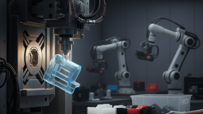
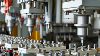
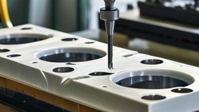
10 Tips for Successful Plastic Part Manufacturing
Successful plastic part manufacturing rarely begins with a machine setting. It begins with a clear part purpose, realistic tolerances, and a moldable design. A glossy prototype may look impressive, yet it can hide sink marks, weld lines, trapped air, or weak corners. Production exposes those weaknesses quickly.
Robert A. Malloy, author of Plastic Part Design for Injection Molding, wrote, “The most important aspect of injection molding is the design of the part.” That principle still guides experienced engineers. Wall thickness, draft angles, ribs, bosses, material flow, and shrinkage must work together before steel is cut. Small design decisions can affect cycle time, tooling cost, assembly quality, and long-term reliability.
This guide presents 10 practical tips for successful plastic part manufacturing. It connects design reviews with material selection, mold construction, process control, inspection, and continuous improvement. The advice applies to prototypes and high-volume production, but no checklist replaces testing. Conditions change.
A resin that performs well in one housing may fail in another. A tolerance that seems reasonable may become expensive after molding trials. Even experienced teams sometimes overlook a tiny sharp corner or an uneven wall near a screw boss. That is where disciplined review matters.
Expect useful direction, not perfect formulas. Measure actual parts. Record defects. Challenge assumptions. The strongest manufacturing process is not the one that looks flawless on paper, but the one that learns quickly from real production evidence.
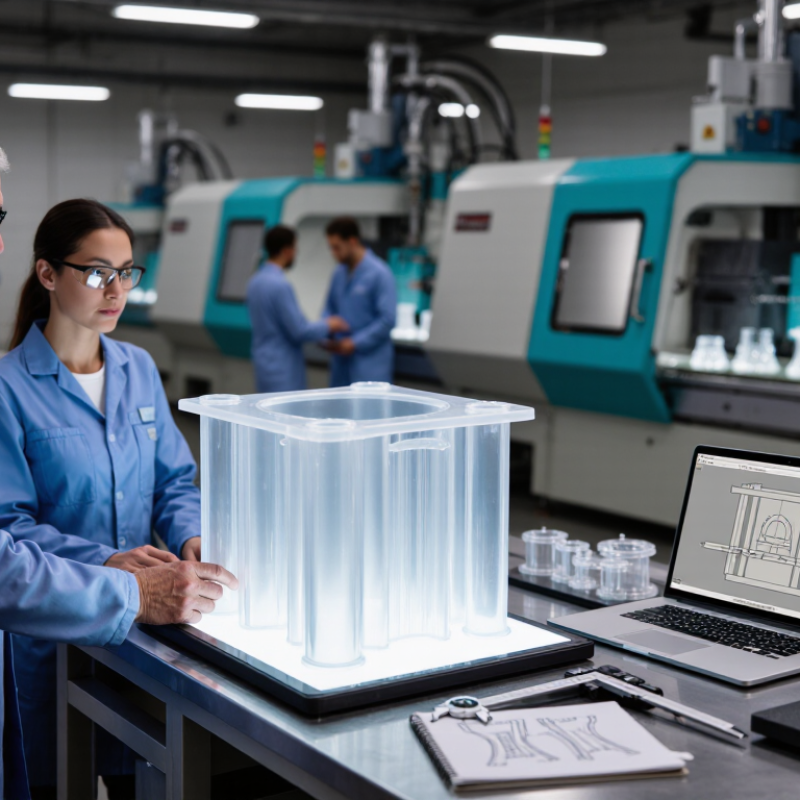
Define Product Requirements and Performance Criteria
Successful plastic part manufacturing starts before the mold is designed. Product requirements should describe the part’s job in measurable terms. State the expected load, temperature range, service life, and acceptable deformation. “Strong” is not enough. A housing may need to survive a 500 N compression force for 10,000 cycles. A clip may require repeated deflection without cracking. These details guide material selection, wall thickness, ribs, and joining methods.
Performance criteria must reflect real use, not only laboratory convenience.
Consider moisture, cleaning chemicals, ultraviolet exposure, friction, and sudden impact. Define dimensional tolerances around function. A tight tolerance everywhere can increase cost without improving performance. Seal areas, snap fits, and alignment features deserve closer control. Include appearance requirements too, such as gloss variation, weld-line visibility, and allowable sink marks.
Document how each requirement will be verified.
Specify test equipment, sample quantity, conditioning time, and pass-fail limits. In one development project, the part passed a short load test but warped after heat exposure. The original criteria missed that condition. That assumption was wrong. Prototypes should be tested with production-like resin, tooling, and assembly forces. Record failures honestly, even when they challenge the design schedule. Requirements may need revision after testing, but every change should have an owner, date, and technical reason.
Select Suitable Plastics and Additives for the Application
For successful plastic part manufacturing, material selection should begin with the application, not the mold. Identify temperature, impact, moisture, chemical exposure, and expected service life. A housing near a heat source may need heat-stable engineering plastic, while a flexible seal may require an elastomeric grade. Small details matter. Wall thickness, assembly stress, and surface finish can change the best choice.
Additives must solve a defined problem. Glass fiber can improve stiffness, but it may increase warpage and wear on tooling. UV stabilizers help outdoor parts, while flame retardants can affect flow, color, and mechanical strength. Too much filler is not automatically better. I once saw a rigid component crack around a screw boss because the selected compound ignored local stress. The material met its basic datasheet values, yet the design and additive package worked poorly together.
Review the technical datasheet, safety information, processing range, and test method before approval. Request sample parts, not only resin pellets, and test them under realistic temperature and humidity cycles. Check shrinkage, weld lines, torque retention, and dimensional change after conditioning. It looked fine. Later, moisture caused assembly problems. That experience reinforced a simple practice: validate the complete material, additive, mold, and process combination before committing to production. Recheck the choice when the application changes, even slightly.
Develop Accurate Molds and Validate Tooling Performance
Accurate molds are the foundation of reliable plastic part manufacturing. Small errors in cavity dimensions can create visible defects, weak walls, or difficult assembly. Engineers should define shrinkage, draft angles, wall thickness, and cooling requirements before cutting steel. A detailed tolerance plan prevents assumptions from becoming expensive rework.
The mold should reflect real production conditions. Check resin flow with simulation, then confirm it through physical trials. During the first test, inspect short shots, weld lines, sink marks, flash, and ejection damage. Measure critical features with calibrated equipment, not visual judgment alone. Record mold temperature, injection pressure, cooling time, and cycle time for every sample. Useful evidence beats confident opinions.
Tooling validation should include repeated cycles, not one successful part. Run the mold until temperatures stabilize and operators can load and remove parts consistently. Inspect samples from different cavities and production stages. A practical weakness is often overlooked: cooling channels may perform well during a short trial but fail after hours of operation. I have found that simple checks, such as monitoring cycle drift and weighing parts, can reveal this early. The first mold revision may still be imperfect. That is normal. Treat each defect as data, review the cause, and update the process window before full production. Keep dimensional reports, maintenance records, and approved samples together for future audits.